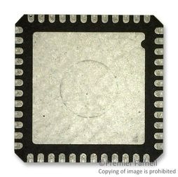
SAMR21 48PIN 256K 85C T&R MAC ADDR, ATSAMR21G18A-MUTA6, Microchip

The SMART SAM R21 is a series of low-power microcontrollers using the 32-bit ARM Cortex -M0+ processor and an integrated ultra-low power 2.4GHz ISM band transceiver. SAM R21 devices are available in 32- and 48-pin packages with up to 256KB Flash, 32KB of SRAM and are operating at a maximum frequency of 48MHz and reach 2.46 Coremark/MHz They are designed for simple and intuitive migration with identical peripheral modules, hex compatible code, identical linear address map and pin compatible migration paths between all devices in the product series. All devices include intelligent and flexible peripherals, Event System for inter-peripheral signaling, and support for capacitive touch button, slider and wheel user interfaces. All devices have accurate and low-power external and internal oscillators. All oscillators can be used as a source for the system clock. Different clock domains can be independently configured to run at different frequencies, enabling power saving by running each peripheral at its optimal clock frequency, and thus maintaining a high CPU frequency while reducing power consumption. The SAM R21 devices have two software-selectable sleep modes, idle and standby. In idle mode the CPU is stopped while all other functions can be kept running. In standby all clocks and functions are stopped expect those selected to continue running. The device supports SleepWalking, which is the module"s ability to wake itself up and wake up its own clock, and hence perform predefined tasks without waking up the CPU. The CPU can then be only woken on a need basis, e.g. a threshold is crossed or a result is ready. The Event System supports synchronous and asynchronous events, allowing peripherals to receive, react to and send events even in standby mode. The Flash program memory can be reprogrammed in-system through the SWD interface. The same interface can be used for non-intrusive on-chip debug of application code. A boot loader running in the device can use any communication interface to download and upgrade the application program in the Flash memory.

  • Processor
    • ARM Cortex-M0+ CPU running at up to 48MH
    • Single-cycle hardware multiplier
    • Micro Trace Buffer (MTB)
  • Memories
    • 768(1)/256/128/64KB in-system self-programmable Flash
    • 32/16/8KB SRAM
  • System
    • Power-on reset (POR) and brown-out detection (BOD)
    • Internal and external clock options with 48MH
    • Digital Frequency Locked Loop (DFLL48M) and 48MH
    • to 96MH
    • Fractional Digital Phase Locked Loop (FDPLL96M)
    • External Interrupt Controller (EIC)
    • Up to 15 external interrupts
    • One non-mask able interrupt
    • Two-pin Serial Wire Debug (SWD) programming, test and debugging interface
  • Low Power
    • Idle and standby sleep modes
    • SleepWalking peripherals
  • Peripherals
    • 12-channel Direct Memory Access Controller (DMAC)
    • 12-channel Event System
    • Integrated Ultra Low Power Transceiver for 2.4GH
    • ISM Band
    • Supported PSDU Data rates: 250kb/s, 500kb/s, 1000kb/s and 2000kb/s(2)
    • -99dBm RX Sensitivity; TX Output Power up to +4dBm
    • Hardware Assisted MAC (Auto-Acknowledge, Auto-Retry)
    • SFD-Detection; Spreading; De-Spreading; Framing; CRC-16 Computation
    • Antenna Diversity and TX/RX Control
    • 128 Byte TX/RX Frame Buffer
    • Integrated 16MH
    • Crystal Oscillator (external crystal needed)
    • PLL synthesi
    • er with 5 MH
    • and 500 kHz
    • channel spacing for 2.4GH
    • ISM band
    • Hardware Security (AES, True Random Generator)
    • Three 16-bit Timer/Counters (TC), configurable as either:
    • One 16-bit TC with compare/capture channels
    • One 8-bit TC with compare/capture channels
    • One 32-bit TC with compare/capture channels, by using two TCs
    • Three 16-bit Timer/Counters for Control (TCC), with extended functions:
    • Up to four compare channels with optional complementary output
    • Generation of synchroni
    • ed pulse width modulation (PWM) pattern across port pins
    • Deterministic fault protection, fast decay and configurable dead-time between complementary output
    • Dithering that increase resolution with up to 5 bit and reduce quanti
    • ation error
    • 32-bit Real Time Counter (RTC) with clock/calendar function
    • Watchdog Timer (WDT)
    • CRC-32 generator
    • One full-speed (12Mbps) Universal Serial Bus (USB) 2.0 interface
    • Embedded host and device function
    • Eight endpoints
    • Up to five Serial Communication Interfaces (SERCOM), each configurable to operate as either:
    • USART with full-duplex and single-wire half-duplex configuration
    • I²C up to 3.4MH
    • SPI
    • LIN slave
    • One 12-bit, 350ksps Analog-to-Digital Converter (ADC) with up to eight external channels
    • Differential and single-ended input
    • 1/2x to 16x programmable gain stage
Характеристики

Program_memory_type

Flash

Specifications

https://4donline.ihs.com/images/VipMasterIC/IC/MCHP/MCHP-S-A0009394157/MCHP-S-A0009394071-1.pdf?hkey=52A5661711E402568146F3353EA87419

Screening_level

Industrial

Schedule_b

8525601025

Ram_size

4 KB

Program_memory_size

32 Kb

Packaging

Tape and Reel

Operating_temperature

-40 to 85 °C

Operating_supply_voltage

2.5, 3.3 V

Watchdog

1

Analog_comparators

2

Eccn

5A992.C

Instruction_set_architecture

RISC

Htsn

8542310001

Family

ATSAMR21G18A

Тип интерфейса

I2C/SPI/UART/USART/USB

Device_core

ARM Cortex M0+

Data_memory_size

16384 byte

Data_bus_width

32 Bit

Country_of_origin

China

Бренд

On_chip_adc

8-chx12-bit

Min_operating_supply_voltage

1.8 V

Number_of_timers

6

Number_of_programmable_i_os

28

Mounting

Surface Mount

Max_speed

48 MHz

Max_operating_supply_voltage

3.6 V

Артикул: ATSAMR21G18A-MUTA6

Описание

The SMART SAM R21 is a series of low-power microcontrollers using the 32-bit ARM Cortex -M0+ processor and an integrated ultra-low power 2.4GHz ISM band transceiver. SAM R21 devices are available in 32- and 48-pin packages with up to 256KB Flash, 32KB of SRAM and are operating at a maximum frequency of 48MHz and reach 2.46 Coremark/MHz They are designed for simple and intuitive migration with identical peripheral modules, hex compatible code, identical linear address map and pin compatible migration paths between all devices in the product series. All devices include intelligent and flexible peripherals, Event System for inter-peripheral signaling, and support for capacitive touch button, slider and wheel user interfaces. All devices have accurate and low-power external and internal oscillators. All oscillators can be used as a source for the system clock. Different clock domains can be independently configured to run at different frequencies, enabling power saving by running each peripheral at its optimal clock frequency, and thus maintaining a high CPU frequency while reducing power consumption. The SAM R21 devices have two software-selectable sleep modes, idle and standby. In idle mode the CPU is stopped while all other functions can be kept running. In standby all clocks and functions are stopped expect those selected to continue running. The device supports SleepWalking, which is the module"s ability to wake itself up and wake up its own clock, and hence perform predefined tasks without waking up the CPU. The CPU can then be only woken on a need basis, e.g. a threshold is crossed or a result is ready. The Event System supports synchronous and asynchronous events, allowing peripherals to receive, react to and send events even in standby mode. The Flash program memory can be reprogrammed in-system through the SWD interface. The same interface can be used for non-intrusive on-chip debug of application code. A boot loader running in the device can use any communication interface to download and upgrade the application program in the Flash memory.

  • Processor
    • ARM Cortex-M0+ CPU running at up to 48MH
    • Single-cycle hardware multiplier
    • Micro Trace Buffer (MTB)
  • Memories
    • 768(1)/256/128/64KB in-system self-programmable Flash
    • 32/16/8KB SRAM
  • System
    • Power-on reset (POR) and brown-out detection (BOD)
    • Internal and external clock options with 48MH
    • Digital Frequency Locked Loop (DFLL48M) and 48MH
    • to 96MH
    • Fractional Digital Phase Locked Loop (FDPLL96M)
    • External Interrupt Controller (EIC)
    • Up to 15 external interrupts
    • One non-mask able interrupt
    • Two-pin Serial Wire Debug (SWD) programming, test and debugging interface
  • Low Power
    • Idle and standby sleep modes
    • SleepWalking peripherals
  • Peripherals
    • 12-channel Direct Memory Access Controller (DMAC)
    • 12-channel Event System
    • Integrated Ultra Low Power Transceiver for 2.4GH
    • ISM Band
    • Supported PSDU Data rates: 250kb/s, 500kb/s, 1000kb/s and 2000kb/s(2)
    • -99dBm RX Sensitivity; TX Output Power up to +4dBm
    • Hardware Assisted MAC (Auto-Acknowledge, Auto-Retry)
    • SFD-Detection; Spreading; De-Spreading; Framing; CRC-16 Computation
    • Antenna Diversity and TX/RX Control
    • 128 Byte TX/RX Frame Buffer
    • Integrated 16MH
    • Crystal Oscillator (external crystal needed)
    • PLL synthesi
    • er with 5 MH
    • and 500 kHz
    • channel spacing for 2.4GH
    • ISM band
    • Hardware Security (AES, True Random Generator)
    • Three 16-bit Timer/Counters (TC), configurable as either:
    • One 16-bit TC with compare/capture channels
    • One 8-bit TC with compare/capture channels
    • One 32-bit TC with compare/capture channels, by using two TCs
    • Three 16-bit Timer/Counters for Control (TCC), with extended functions:
    • Up to four compare channels with optional complementary output
    • Generation of synchroni
    • ed pulse width modulation (PWM) pattern across port pins
    • Deterministic fault protection, fast decay and configurable dead-time between complementary output
    • Dithering that increase resolution with up to 5 bit and reduce quanti
    • ation error
    • 32-bit Real Time Counter (RTC) with clock/calendar function
    • Watchdog Timer (WDT)
    • CRC-32 generator
    • One full-speed (12Mbps) Universal Serial Bus (USB) 2.0 interface
    • Embedded host and device function
    • Eight endpoints
    • Up to five Serial Communication Interfaces (SERCOM), each configurable to operate as either:
    • USART with full-duplex and single-wire half-duplex configuration
    • I²C up to 3.4MH
    • SPI
    • LIN slave
    • One 12-bit, 350ksps Analog-to-Digital Converter (ADC) with up to eight external channels
    • Differential and single-ended input
    • 1/2x to 16x programmable gain stage

Детали

Program_memory_type

Flash

Specifications

https://4donline.ihs.com/images/VipMasterIC/IC/MCHP/MCHP-S-A0009394157/MCHP-S-A0009394071-1.pdf?hkey=52A5661711E402568146F3353EA87419

Screening_level

Industrial

Schedule_b

8525601025

Ram_size

4 KB

Program_memory_size

32 Kb

Packaging

Tape and Reel

Operating_temperature

-40 to 85 °C

Operating_supply_voltage

2.5, 3.3 V

Watchdog

1

Analog_comparators

2

Eccn

5A992.C

Instruction_set_architecture

RISC

Htsn

8542310001

Family

ATSAMR21G18A

Тип интерфейса

I2C/SPI/UART/USART/USB

Device_core

ARM Cortex M0+

Data_memory_size

16384 byte

Data_bus_width

32 Bit

Country_of_origin

China

Бренд

On_chip_adc

8-chx12-bit

Min_operating_supply_voltage

1.8 V

Number_of_timers

6

Number_of_programmable_i_os

28

Mounting

Surface Mount

Max_speed

48 MHz

Max_operating_supply_voltage

3.6 V