Описание
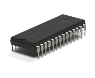
PIC18LC252 come in 28-pin and 40-pin packages. The 28-pin devices do not have a Parallel Slave Port (PSP) implemented and the number of Analog-toDigital (A/D) converter input channels is reduced to 5 For timing insensitive applications, the “RC” and “RCIO” device options offer additional cost savings. The RC oscillator frequency is a function of the supply voltage, the resistor (REXT) and capacitor (CEXT) values and the operating temperature. In addition to this, the oscillator frequency will vary from unit to unit due to normal process parameter variation. Furthermore, the difference in lead frame capacitance between package types will also affect the oscillation frequency, especially for low CEXT values. The user also needs to take into account variation due to tolerance of external R and C components used In the RC oscillator mode, the oscillator frequency divided by 4 is available on the OSC2 pin. This signal may be used for test purposes or to synchronize other logic. The RCIO oscillator mode functions like the RC mode, except that the OSC2 pin becomes an additional general purpose I/O pin. The I/O pin becomes bit 6 of PORTA (RA6) The EC and ECIO oscillator modes require an external clock source to be connected to the OSC1 pin. The feedback device between OSC1 and OSC2 is turned off in these modes to save current. There is no oscillator start-up time required after a Power-on Reset or after a recovery from SLEEP mode.In the EC oscillator mode, the oscillator frequency divided by 4 is available on the OSC2 pin. This signal may be used for test purposes or to synchronize other logic The ECIO oscillator mode functions like the EC mode, except that the OSC2 pin becomes an additional general purpose I/O pin. The I/O pin becomes bit 6 of PORTA (RA6). A Phase Locked Loop circuit is provided as a programmable option for users that want to multiply the frequency of the incoming crystal oscillator signal by 4. For an input clock frequency of 10 MHz, the internal clock frequency will be multiplied to 40 MHz. This is useful for customers who are concerned with EMI due to high frequency crystals. The PLL can only be enabled when the oscillator configuration bits are programmed for HS mode. If they are programmed for any other mode, the PLL is not enabled and the system clock will come directly from OSC1. The PLL is one of the modes of the FOSC<2:0> configuration bits. The oscillator mode is specified during device programming. A PLL lock timer is used to ensure that the PLL has locked before device execution starts. The PLL lock timer has a time-out that is called TPLL
- High Performance RISC CPU:
- C compiler optimized architecture/instruction set
- Source code compatible with the PIC16CXX instruction set
- Linear program memory addressing to 2 Mbytes
- Linear data memory addressing to 4 Kbytes
- Up to 10 MIPs operation:
- DC 40 MHz osc./clock input
- 4 MHz 10 MHz osc./clock input with PLL active
- 16-bit wide instructions, 8-bit wide data path
- Priority levels for interrupts
- 8 x 8 Single Cycle Hardware Multiplier Peripheral Features:
- High current sink/source 25 mA/25 mA
- Three external interrupt pins
- Timer0 module: 8-bit/16-bit timer/counter with 8-bit programmable prescaler
- Timer1 module: 16-bit timer/counter
- Timer2 module: 8-bit timer/counter with 8-bit period register (time-base for PWM)
- Timer3 module: 16-bit timer/counter
- Secondary oscillator clock option Timer1/Timer3
- Two Capture/Compare/PWM (CCP) modules. CCP pins that can be configured as:
- Capture input: capture is 16-bit, max. resolution 6.25 ns (TCY/16)
- Compare is 16-bit, max. resolution 100 ns (TCY)
- PWM output: PWM resolution is 1 to 10-bit. Max. PWM freq. @: 8-bit resolution = 156 kHz 10-bit resolution = 39 kHz
- Master Synchronous Serial Port (MSSP) module. Two modes of operation:
- 3-wire SPI™ (supports all 4 SPI modes)
- I2C™ master and slave mode
- Addressable USART module:
- Supports interrupt on Address bit
- Parallel Slave Port (PSP) module Analog Features:
- Compatible 10-bit Analog-to-Digital Converter module (A/D) with:
- Fast sampling rate
- Conversion available during SLEEP
- DNL = ±1 LSb, INL = ±1 LSb
- Programmable Low Voltage Detection (LVD) module
- Supports interrupt-on-low voltage detection
- Programmable Brown-out Reset (BOR) Special Microcontroller Features:
- Power-on Reset (POR), Power-up Timer (PWRT) and Oscillator Start-up Timer (OST)
- Watchdog Timer (WDT) with its own on-chip RC oscillator for reliable operation
- Programmable code protection
- Power saving SLEEP mode
- Selectable oscillator options including:
- 4X Phase Lock Loop (of primary oscillator)
- Secondary Oscillator (32 kHz) clock input
- In-Circuit Serial Programming (ICSP™) via two pins CMOS Technology:
- Low power, high speed EPROM technology
- Fully static design
- Wide operating voltage range (2.5V to 5.5V)
- Industrial and Extended temperature ranges
- Low power consumption