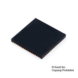
MCU 32-Bit MB9B120L ARM Cortex M3 RISC 288KB Flash 3.3V/5V 64-Pin QFN, MB9BF124LQN-G-AVE2, Rochester Electronics

The MB9BF124L is a highly integrated 32-bit microcontrollers dedicated for embedded controllers with low-power consumption mode and competitive cost. These series are based on the ARM Cortex-M3 Processor with on-chip Flash memory and SRAM, and have peripheral functions such as various timers, ADCs, DACs and Communication Interfaces (UART, CSIO, I2C, LIN).

  • 32-bit ARM Cortex-M3 Core
    • Processor version: r2p1
    • Up to 144MHz Frequency Operation
    • Memory Protection Unit (MPU): improves the reliability of an embedded system
    • Integrated Nested Vectored Interrupt Controller (NVIC): 1 NMI (non-maskable interrupt) and 48 peripheral interrupts and 16 priority levels
    • 24-bit System timer (Sys Tick): System timer for OS task management
  • On-chip Memories [Flash memory] These series are based on two independent on-chip Flash memories.
    • MainFlash
    • Up to 512Kbyte
    • Built-in Flash Accelerator System with 16Kbyte trace buffer memory
    • The read access to Flash memory can be achieved without wait cycle up to operation frequency of 72MHz. Even at the operation frequency more than 72MHz, an equivalent access to Flash memory can be obtained by Flash Accelerator System.
    • Security function for code protection
    • WorkFlash
    • 32Kbyte
    • Read cycle
    • 4wait-cycle: the operation frequency more than 72MHz
    • 2wait-cycle: the operation frequency more than 40MHz, and to 72MHz
    • 0wait-cycle: the operation frequency to 40MHz
    • Security function is shared with code protection [SRAM] This Series contain a total of up to 64Kbyte on-chip SRAM memories. This is composed of two independent SRAM (SRAM0, SRAM1). SRAM0 is connected to I-code bus or D-code bus of Cortex-M3 core. SRAM1 is connected to System bus.
    • SRAM0: Up to 32 Kbyte
    • SRAM1: Up to 32 Kbyte
  • DMA Controller (8channels) DMA Controller has an independent bus for CPU, so CPU and DMA Controller can process simultaneously.
    • 8 independently configured and operated channels
    • Transfer can be started by software or request from the built-in peripherals
    • Transfer address area: 32bit (4Gbyte)
    • Transfer mode: Block transfer/Burst transfer/Demand transfer
    • Transfer data type: byte/half-word/word
    • Transfer block count: 1 to 16
    • Number of transfers: 1 to 65536
  • A/D Converter (Max 16channels) [12-bit A/D Converter]
    • Successive Approximation Register type
    • Built-in 3unit
    • Conversion time: 1.0 us@5V
    • Priority conversion available (priority at 2 levels)
    • Scanning conversion mode
    • Built-in FIFO for conversion data storage (for SCAN conversion: 16steps, for Priority conversion: 4steps)
  • Base Timer (Max 8channels) Operation mode is selectable from the followings for each channel.
    • 16-bit PWM timer
    • 16-bit PPG timer
    • 16/32-bit reload timer
    • 16/32-bit PWC timer , General Purpose I/O Port This series can use its pins as general purpose I/O ports when they are not used for external bus or peripherals. Moreover, the port relocate function is built in. It can set which I/O port the peripheral function can be allocated.
    • Capable of pull-up control per pin
    • Capable of reading pin level directly
    • Built-in the port relocate function
    • Up 103 fast general purpose I/O Ports@120pin Package
  • Multi-function Timer (Max 3units) The Multi-function timer is composed of the following blocks.
    • 16-bit free-run timer – 3ch./unit
    • Input capture – 4ch./unit
    • Output compare – ch./unit
    • A/D activating compare – 3ch./unit
    • Waveform generator – 3ch./unit
    • 16-bit PPG timer – 3ch./unit The following function can be used to achieve the motor control.
    • PWM signal output function
    • DC chopper waveform output function
    • Dead time function
    • Input capture function
    • A/D convertor activate function
    • DTIF (Motor emergency stop) interrupt function.

Характеристики

Product_dimensions

9 x 9 x 0.8

Htsn

8542310001

Program_memory_type

Flash

Pin_count

64

Operating_temperature

-40 to 105 °C

Operating_supply_voltage

3.3, 5 V

Specifications

https://4donline.ihs.com/images/VipMasterIC/IC/CYPR/CYPR-S-A0006313869/CYPR-S-A0006313913-1.pdf?hkey=52A5661711E402568146F3353EA87419

On_chip_dac

2-chx10-bit

Number_of_timers

3

Schedule_b

8542390000

Device_core

ARM Cortex M3

Eccn

3A991.A

Data_bus_width

32 Bit

Country_of_origin

United States

Бренд

Instruction_set_architecture

RISC

Тип интерфейса

CSIO/I2C/LIN/UART

Number_of_programmable_i_os

50

Max_speed

72 MHz

Mounting

Surface Mount

Артикул: MB9BF124LQN-G-AVE2

Описание

The MB9BF124L is a highly integrated 32-bit microcontrollers dedicated for embedded controllers with low-power consumption mode and competitive cost. These series are based on the ARM Cortex-M3 Processor with on-chip Flash memory and SRAM, and have peripheral functions such as various timers, ADCs, DACs and Communication Interfaces (UART, CSIO, I2C, LIN).

  • 32-bit ARM Cortex-M3 Core
    • Processor version: r2p1
    • Up to 144MHz Frequency Operation
    • Memory Protection Unit (MPU): improves the reliability of an embedded system
    • Integrated Nested Vectored Interrupt Controller (NVIC): 1 NMI (non-maskable interrupt) and 48 peripheral interrupts and 16 priority levels
    • 24-bit System timer (Sys Tick): System timer for OS task management
  • On-chip Memories [Flash memory] These series are based on two independent on-chip Flash memories.
    • MainFlash
    • Up to 512Kbyte
    • Built-in Flash Accelerator System with 16Kbyte trace buffer memory
    • The read access to Flash memory can be achieved without wait cycle up to operation frequency of 72MHz. Even at the operation frequency more than 72MHz, an equivalent access to Flash memory can be obtained by Flash Accelerator System.
    • Security function for code protection
    • WorkFlash
    • 32Kbyte
    • Read cycle
    • 4wait-cycle: the operation frequency more than 72MHz
    • 2wait-cycle: the operation frequency more than 40MHz, and to 72MHz
    • 0wait-cycle: the operation frequency to 40MHz
    • Security function is shared with code protection [SRAM] This Series contain a total of up to 64Kbyte on-chip SRAM memories. This is composed of two independent SRAM (SRAM0, SRAM1). SRAM0 is connected to I-code bus or D-code bus of Cortex-M3 core. SRAM1 is connected to System bus.
    • SRAM0: Up to 32 Kbyte
    • SRAM1: Up to 32 Kbyte
  • DMA Controller (8channels) DMA Controller has an independent bus for CPU, so CPU and DMA Controller can process simultaneously.
    • 8 independently configured and operated channels
    • Transfer can be started by software or request from the built-in peripherals
    • Transfer address area: 32bit (4Gbyte)
    • Transfer mode: Block transfer/Burst transfer/Demand transfer
    • Transfer data type: byte/half-word/word
    • Transfer block count: 1 to 16
    • Number of transfers: 1 to 65536
  • A/D Converter (Max 16channels) [12-bit A/D Converter]
    • Successive Approximation Register type
    • Built-in 3unit
    • Conversion time: 1.0 us@5V
    • Priority conversion available (priority at 2 levels)
    • Scanning conversion mode
    • Built-in FIFO for conversion data storage (for SCAN conversion: 16steps, for Priority conversion: 4steps)
  • Base Timer (Max 8channels) Operation mode is selectable from the followings for each channel.
    • 16-bit PWM timer
    • 16-bit PPG timer
    • 16/32-bit reload timer
    • 16/32-bit PWC timer , General Purpose I/O Port This series can use its pins as general purpose I/O ports when they are not used for external bus or peripherals. Moreover, the port relocate function is built in. It can set which I/O port the peripheral function can be allocated.
    • Capable of pull-up control per pin
    • Capable of reading pin level directly
    • Built-in the port relocate function
    • Up 103 fast general purpose I/O Ports@120pin Package
  • Multi-function Timer (Max 3units) The Multi-function timer is composed of the following blocks.
    • 16-bit free-run timer – 3ch./unit
    • Input capture – 4ch./unit
    • Output compare – ch./unit
    • A/D activating compare – 3ch./unit
    • Waveform generator – 3ch./unit
    • 16-bit PPG timer – 3ch./unit The following function can be used to achieve the motor control.
    • PWM signal output function
    • DC chopper waveform output function
    • Dead time function
    • Input capture function
    • A/D convertor activate function
    • DTIF (Motor emergency stop) interrupt function.

Детали

Product_dimensions

9 x 9 x 0.8

Htsn

8542310001

Program_memory_type

Flash

Pin_count

64

Operating_temperature

-40 to 105 °C

Operating_supply_voltage

3.3, 5 V

Specifications

https://4donline.ihs.com/images/VipMasterIC/IC/CYPR/CYPR-S-A0006313869/CYPR-S-A0006313913-1.pdf?hkey=52A5661711E402568146F3353EA87419

On_chip_dac

2-chx10-bit

Number_of_timers

3

Schedule_b

8542390000

Device_core

ARM Cortex M3

Eccn

3A991.A

Data_bus_width

32 Bit

Country_of_origin

United States

Бренд

Instruction_set_architecture

RISC

Тип интерфейса

CSIO/I2C/LIN/UART

Number_of_programmable_i_os

50

Max_speed

72 MHz

Mounting

Surface Mount