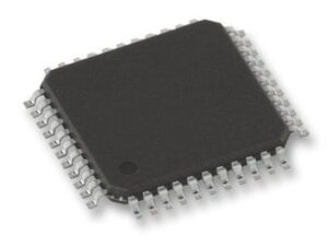
MCU 8-bit AT89 8051 CISC 32KB Flash 3.3V/5V 44-Pin VQFP Tray, AT89C51CC01CA-RLTUM, Microchip

The T89C51CC01 is the first member of the CANaryTM family of 8-bit microcontrollers dedicated to CAN network applications. In X2 mode a maximum external clock rate of 20 MHz reaches a 300 ns cycle time. Besides the full CAN controller T89C51CC01 provides 32K Bytes of Flash memory including In-System-Programming (ISP), 2K Bytes Boot Flash Memory, 2K Bytes EEPROM and 1.2-Kbyte RAM.

  • 80C51 Core Architecture
  • 256 Bytes of On-chip RAM
  • 1K Bytes of On-chip XRAM
  • 32K Bytes of On-chip Flash Memory
    • Data Retention: 10 Years at 85°C Erase/Write Cycle: 100K
  • Boot Code with Independent Lock Bits
  • 2K Bytes of On-chip Flash for Boot loader
  • In-System Programming by On-Chip Boot Program (CAN, UART) and IAP Capability
  • 2K Bytes of On-chip EEPROM Erase/Write Cycle: 100K
  • 14-sources 4-level Interrupts
  • Three 16-bit Timers/Counters
  • Full Duplex UART Compatible 80C51
  • Maximum Crystal Frequency 40 MHz, in X2 Mode, 20 MHz (CPU Core, 20 MHz)
  • Five Ports: 32 + 2 Digital I/O Lines
  • Five-channel 16-bit PCA with:
    • PWM (8-bit)
    • High-speed Output
    • Timer and Edge Capture
  • Double Data Pointer
  • 21-bit Watchdog Timer (7 Programmable Bits)
  • A 10-bit Resolution Analog to Digital Converter (ADC) with 8 Multiplexed Inputs
  • Full CAN Controller:
    • Fully Compliant with CAN Rev2.0A and 2.0B
    • Optimized Structure for Communication Management (Via SFR)
    • 15 Independent Message Objects: Each Message Object Programmable on Transmission or Reception Individual Tag and Mask Filters up to 29-bit Identifier/Channel 8-byte Cyclic Data Register (FIFO)/Message Object 16-bit Status and Control Register/Message Object 16-bit Time-Stamping Register/Message Object CAN Specification 2.0 Part A or 2.0 Part B Programmable for Each Message Object Access to Message Object Control and Data Registers Via SFR Programmable Reception Buffer Length Up To 15 Message Objects Priority Management of Reception of Hits on Several Message Objects at the Same Time (Basic CAN Feature) Priority Management for Transmission Message Object Overrun Interrupt
    • Supports: Time Triggered Communication Auto baud and Listening Mode Programmable Automatic Reply Mode
    • 1-Mbit/s Maximum Transfer Rate at 8 MHz (1) Crystal Frequency in X2 Mode
    • Readable Error Counters
    • Programmable Link to On-chip Timer for Time Stamping and Network Synchronization
    • Independent Baud Rate Prescaler
    • Data, Remote, Error and Overload Frame Handling
  • On-chip Emulation Logic (Enhanced Hook System)
  • Power Saving Modes:
    • Idle Mode
    • Power-down Mode

Характеристики

Бренд

Operating_supply_voltage

3.3, 5 V

Min_operating_supply_voltage

3 V

Max_operating_supply_voltage

5.5 V

Supplier_package

VQFP

Specifications

https://4donline.ihs.com/images/VipMasterIC/IC/ATML/ATMLS04760/ATMLS04760-1.pdf?hkey=52A5661711E402568146F3353EA87419

Special_features

CAN Controller,Programmable Counter Array

Screening_level

Industrial

Schedule_b

8542310000

Ram_size

1.25 KB

Program_memory_type

Flash

Program_memory_size

32 Kb

Product_dimensions

10.1 x 10.1 x 1.45 mm

Pin_count

44

Operating_temperature

-40 to 85 °C

On_chip_adc

8-chx10-bit

Country_of_origin

Philippines

Number_of_timers

3

Number_of_programmable_i_os

34

Msl_level

3

Mounting

Surface Mount

Maximum_speed

40 MHz

Max_processing_temp

260

Lead_finish

Matte Tin

Тип интерфейса

CAN/UART

Instruction_set_architecture

CISC

Htsn

8542310001

Eccn

3A991.A.2

Device_core

8051

Data_bus_width

8 Bit

Max_power_dissipation

1000 mW

Артикул: AT89C51CC01CA-RLTUM

Описание

The T89C51CC01 is the first member of the CANaryTM family of 8-bit microcontrollers dedicated to CAN network applications. In X2 mode a maximum external clock rate of 20 MHz reaches a 300 ns cycle time. Besides the full CAN controller T89C51CC01 provides 32K Bytes of Flash memory including In-System-Programming (ISP), 2K Bytes Boot Flash Memory, 2K Bytes EEPROM and 1.2-Kbyte RAM.

  • 80C51 Core Architecture
  • 256 Bytes of On-chip RAM
  • 1K Bytes of On-chip XRAM
  • 32K Bytes of On-chip Flash Memory
    • Data Retention: 10 Years at 85°C Erase/Write Cycle: 100K
  • Boot Code with Independent Lock Bits
  • 2K Bytes of On-chip Flash for Boot loader
  • In-System Programming by On-Chip Boot Program (CAN, UART) and IAP Capability
  • 2K Bytes of On-chip EEPROM Erase/Write Cycle: 100K
  • 14-sources 4-level Interrupts
  • Three 16-bit Timers/Counters
  • Full Duplex UART Compatible 80C51
  • Maximum Crystal Frequency 40 MHz, in X2 Mode, 20 MHz (CPU Core, 20 MHz)
  • Five Ports: 32 + 2 Digital I/O Lines
  • Five-channel 16-bit PCA with:
    • PWM (8-bit)
    • High-speed Output
    • Timer and Edge Capture
  • Double Data Pointer
  • 21-bit Watchdog Timer (7 Programmable Bits)
  • A 10-bit Resolution Analog to Digital Converter (ADC) with 8 Multiplexed Inputs
  • Full CAN Controller:
    • Fully Compliant with CAN Rev2.0A and 2.0B
    • Optimized Structure for Communication Management (Via SFR)
    • 15 Independent Message Objects: Each Message Object Programmable on Transmission or Reception Individual Tag and Mask Filters up to 29-bit Identifier/Channel 8-byte Cyclic Data Register (FIFO)/Message Object 16-bit Status and Control Register/Message Object 16-bit Time-Stamping Register/Message Object CAN Specification 2.0 Part A or 2.0 Part B Programmable for Each Message Object Access to Message Object Control and Data Registers Via SFR Programmable Reception Buffer Length Up To 15 Message Objects Priority Management of Reception of Hits on Several Message Objects at the Same Time (Basic CAN Feature) Priority Management for Transmission Message Object Overrun Interrupt
    • Supports: Time Triggered Communication Auto baud and Listening Mode Programmable Automatic Reply Mode
    • 1-Mbit/s Maximum Transfer Rate at 8 MHz (1) Crystal Frequency in X2 Mode
    • Readable Error Counters
    • Programmable Link to On-chip Timer for Time Stamping and Network Synchronization
    • Independent Baud Rate Prescaler
    • Data, Remote, Error and Overload Frame Handling
  • On-chip Emulation Logic (Enhanced Hook System)
  • Power Saving Modes:
    • Idle Mode
    • Power-down Mode

Детали

Бренд

Operating_supply_voltage

3.3, 5 V

Min_operating_supply_voltage

3 V

Max_operating_supply_voltage

5.5 V

Supplier_package

VQFP

Specifications

https://4donline.ihs.com/images/VipMasterIC/IC/ATML/ATMLS04760/ATMLS04760-1.pdf?hkey=52A5661711E402568146F3353EA87419

Special_features

CAN Controller,Programmable Counter Array

Screening_level

Industrial

Schedule_b

8542310000

Ram_size

1.25 KB

Program_memory_type

Flash

Program_memory_size

32 Kb

Product_dimensions

10.1 x 10.1 x 1.45 mm

Pin_count

44

Operating_temperature

-40 to 85 °C

On_chip_adc

8-chx10-bit

Country_of_origin

Philippines

Number_of_timers

3

Number_of_programmable_i_os

34

Msl_level

3

Mounting

Surface Mount

Maximum_speed

40 MHz

Max_processing_temp

260

Lead_finish

Matte Tin

Тип интерфейса

CAN/UART

Instruction_set_architecture

CISC

Htsn

8542310001

Eccn

3A991.A.2

Device_core

8051

Data_bus_width

8 Bit

Max_power_dissipation

1000 mW